# Made the PCB and populated with components the USBtiny ISP programmer I designed earlier.
Will check its working tomorrow
# Made the PCB and populated with components the USBtiny ISP programmer I designed earlier.
Will check its working tomorrow
Did a refresher course on HTML and CSS – in case I need it again.
I need to practice on positioning using CSS
Opened up an electronic energy meter (single phase) to see what is inside. Unfortunately the meter had a protective circuit for tampering and it stopped working once its cover was opened.
Don’t have a camera to post the pics………..but will take pics and post tomorrow.
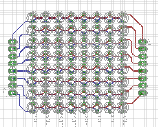
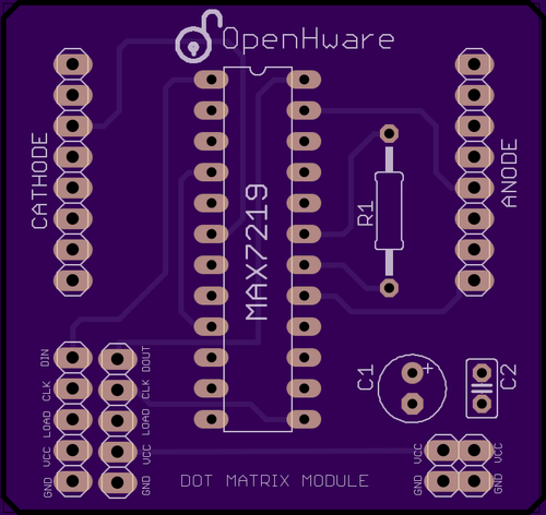
This is rendering of the design for the USB Tiny ISP programmer that I earlier made and tested manually. This design is for fabrication purpose. Hope to order it and get it checked soon. One of our first kits.
TOP VIEW
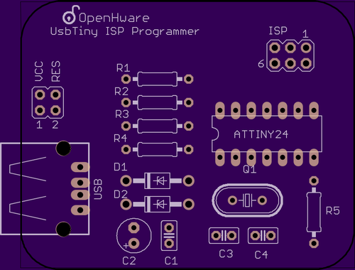
OpenHware USB Tiny ISP Programmer
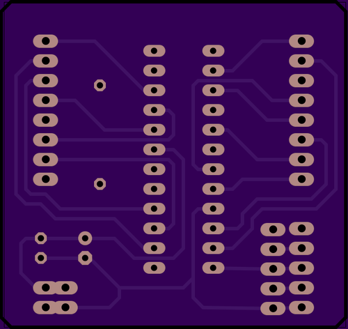
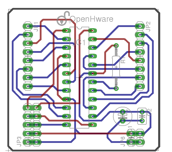
BOTTOM VIEW
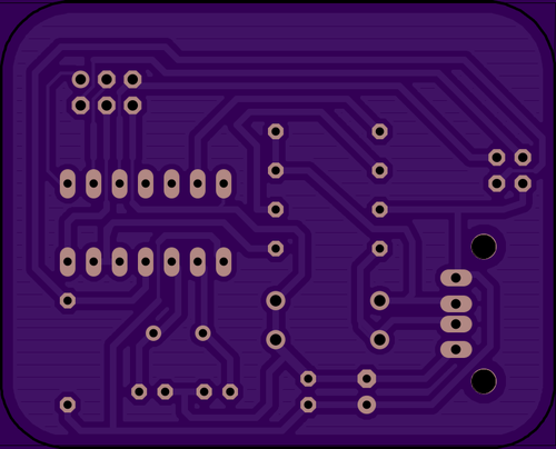
OpenHware UsbTiny ISP Programmer
LED is a PN junction diode. And a PN junction diode when inverted acts as a small capacitance. This property can be used to make LED also behave as a touch sensor – sensitive to human touch. All you need to do is invert the led – charge the capacitance – and measure how long does it take for the capacitance to discharge. Ordinarily it would take some time for the capacitance to discharge – but when you touch the negative lead (+ve end of the led as capacitor) of the LED, our body acts a charge sink and the capacitance discharges quickly. Here is the algorithm: 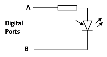 //Discharge any capacitance remaining on the LED Set LeadA Output HIGH Set LeadB Ouptut LOW wait 1ms //Reverse Bias and charge Set LeadA Output LOW Set LeadB Output HIGH wait 1ms //Discharge the capacitance Set Lead B Input LOW Count how long it takes for the LeadB to read low
Attached is the arduino Code for this:
ledAsTouchSensor.ino
There are times when an external mouse comes handy while browsing or while playing an exciting FPS game on a laptop computer. But one doesn’t carry a USB mouse always. Here comes your smartphone to the rescue !
The movement of phone can be mapped to the movement of mouse pointer using Accelerometer present in the phone. Accelerometer data is sent wireless ( the phone and computer being in the same network ). Network can be established using WiFi-Hotspot present in the phone.
The server program runs on the smart phone. It sends Accelerometer data to the client program on the computer, which filters the data and sends corresponding signals to move the mouse pointer.
Currently, a server program has been developed to send X and Y data from the Accelerometer to the client program running on the computer. The client program is written in java. Thanks to Vishal for…
View original post 204 more words
The idea first arose in my mind when I was staying as a paying guest in a room. My room did not have a doorbell and nor could I get it installed without making significant changes in the electrical wiring of my room. Visitors coming, knocking my door and I not realizing it through the sound of the headphones plugged into my ears and playing Linkin Park songs was becoming fairly common.
This led me into thinking of making a DoorKnock module which can be plugged at the back of the door and which will send an alarm to my mobile phone when someone knocks on the door . The module would have a (piezo)sensor to sense the vibration of the knock and a bluetooth module to connect to my mobile phone. Additionally there would be a microcontroller to interface with the sensor and the bluetooth module.
I had most of the materials I needed. I decided to use Arduino for past prototyping and I had to order for a bluetooth module ( I settled for HC06). Here is the hardware circuit for the DoorKNock module I came up with.
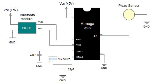
Fig: Hardware circuit for DoorKnock Module
The program in Arduino was a simple one. It would take the analog output data from the piezosensor, convert it to digital data and compare it with a predefined threshold. If the output value crosses a certain threshold – a data ‘test’ would be transmitted through the HC06 bluetooth module to the device (mobile phone) to which it is paired and connected.
The mobile phone should additionally have an application running and listening to the HC06 module. Whenever it receives the data ‘test’ , an alarm should be triggered. Since I had not written this app yet, I decided to test the circuit using my computer.
I paired and connected the HC06 bluetooth module to my computer using my Bluetooth Manager. As soon as the device was connected it formed a serial port called /dev/rfcomm0. I opened my terminal window and entered the command sudo cat /dev/rfcomm0 to have a live display of the data coming to my rfcomm port. Here is what happened when I sent the knock…………..
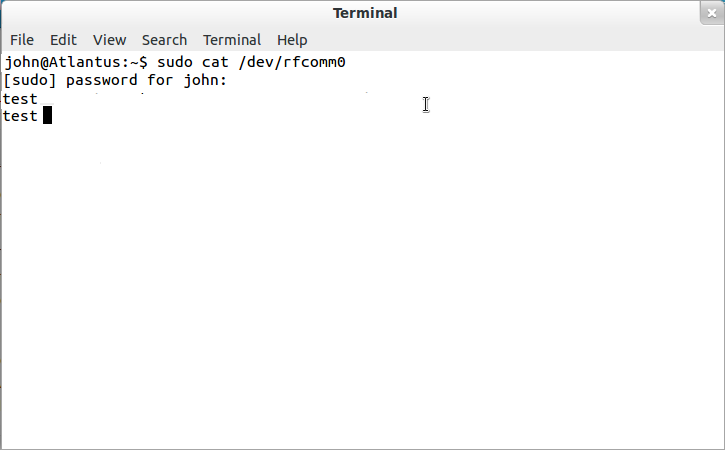
Fig: Screenshot of my terminal when DoorKnock module sends ‘test’ data on knocking
Assured that my hardware module was working properly I approached my junior Aravind Srivatsan to make an Android app that listens to the data sent by the HC06 module. He came up with the app within a week and we tested its working.
Here is how the module looks at the back of my door.
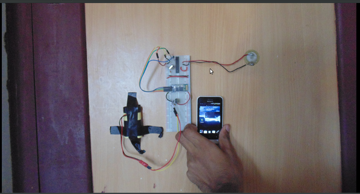
Fig: DoorKnock Module at the back of my door
I will come up with the video to demonstrate its working soon. Additionally you can download the program, app and all the related files regarding DoorKnock module from www.openhware.com
There are lots of ways in which the above module can be improved- for example using interrupts will conserve the battery life. Also, I would prefer using 8051 series of microcontroller for the purpose. I will update the readers on the future developments of this work in my future blogs. Till then Adieu!!